Links
Tags
Knobs, Wiring and Buttons - Progressing on the A320 FCU
I haven't had a lot of time the last few weeks to work on the FCU much further, however there are a couple of updates worth sharing.
Minor redesign to the back plate
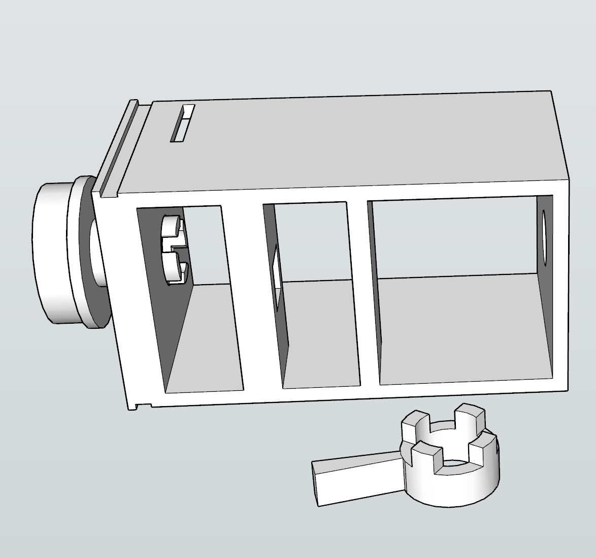
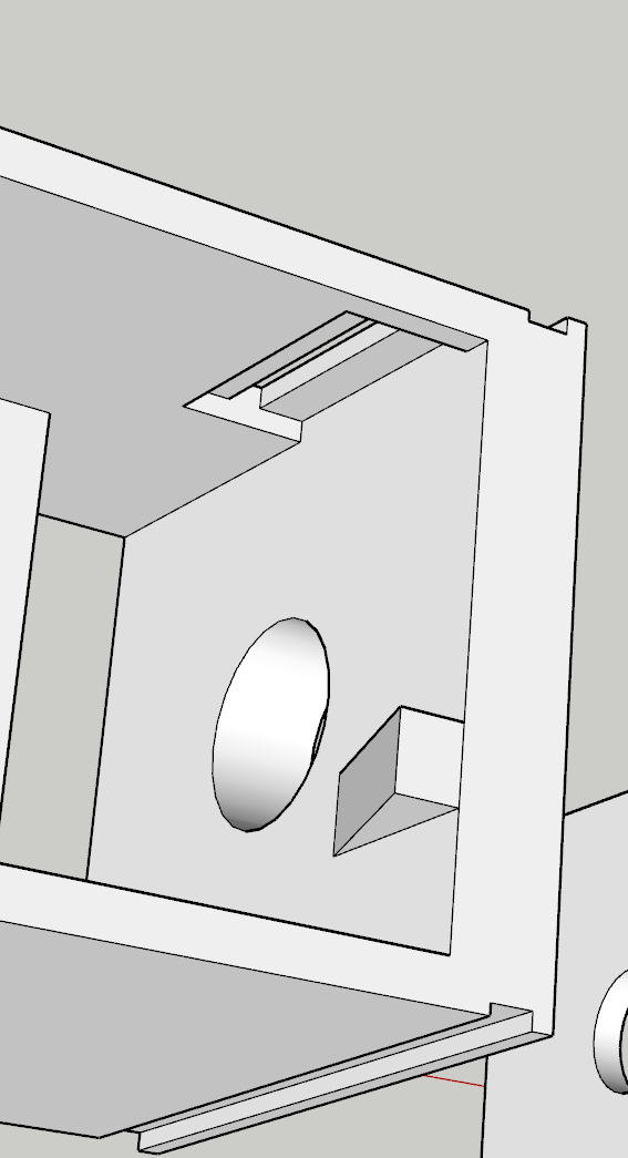
I had this grand idea to make insertable Korry's into place and have them as removable independent units. Unfortunately, those LED lights wouldn't fit inside the chamber I had printed and the outcome wasn't great. To get around the need to glue and design all of those components, I had completed another design - this time where the chamber was integrated to the backplate. As I wasn't too sure about the tolerances here, I had printed a few different sizes to work with the Korry inserts but I really only had one shot at getting the backplate done.
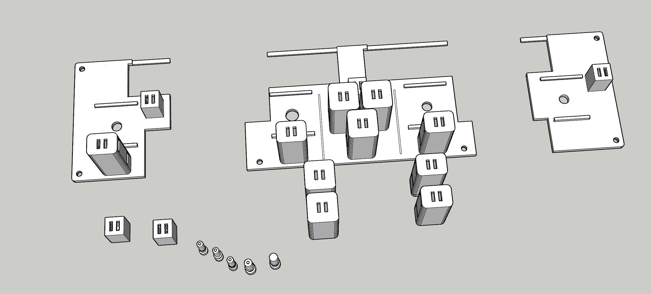
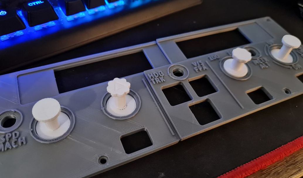
With this out of the way, the next step was to insert buttons and led lights into each of these new chambers. Again, this took several goes that I had pre-empted and thus the creation of different sizes - but thankfully things like leaving a large gap to slip the buttons in really helped out here. It was fiddly though, and you really get to know just how tight (i.e. < 0.1mm inaccuracies) things may fit or require a bit of filing and cutting to get things in snug.
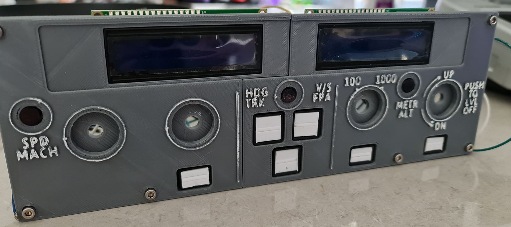
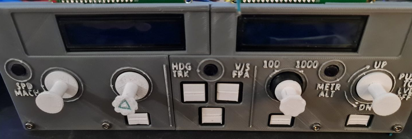
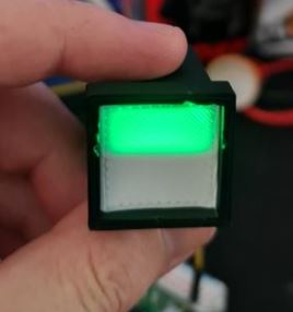
With the screens in place, it's starting to come along.
Installing the Rotary Encoders
I've spent a bit of time going back and forth on getting a good, repeatable push-pull rotary encoder working and in the middle of doing this had learned a few more quirks about the printer - especially printing such small volume items. For the Rotary Encoders in particular, when I began I was printing shells, stalks and knobs altogether with the same material. As I started printing smaller volumes, I started getting stringy mess and prints that wouldn't be loose enough around the rotary encoder itself.
Having not had to level this printer for a few months, I figured at the very least I'd clean up the bed, re-level it manually and give the internals a good clean too (ensure the filament isn't slipping in the extruder from a build-up of gunk). I'd 3D Print a calibration cube and everything was within known tolerances (< 0.1mm on the Z axis but otherwise everything else recorded a perfect 2mm). I had printed a few other things at the same time and they also come out well without stringing. It finally dawned on me that perhaps the part was 'too hot' and wasn't given enough time to 'cool down' before applying the next layer. So to remedy the next print, instead of printing one stalk - I printed all the working parts and things kind of went back to normal.
The reality is that when you start playing with your printer - you start having to 'learn' all the quirks again. Having a more level bed and now knowing about volume of prints to help dissipate heat means you're back to calibrating your software settings to compensate too. So it's fair to say that it took quite a few goes before usable prints were coming out.
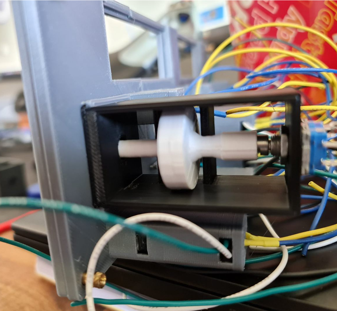
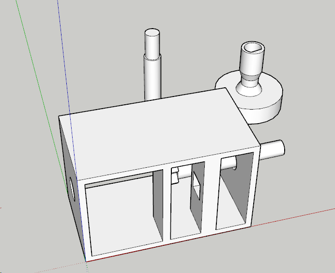
With the first prototype in place things are looking on the up. This particular switch has the right clearance off the button at the back and works perfectly. I perhaps had unrealistic expectations that the same will occur for the other ones - but unfortunately it didn't quite work that way. For the second rotary encoder, the disc didn't quite go all the way down on the rotary encoder so the disc itself in the 'release' mode was touching right up against the pull mechanism - not a great outcome. It's fair to say that in hindsight, I would probably use a longer stalk button to remove that margin of error and perhaps had a bit more of a gap and maybe a spring to help. In any case, something to improve on.
Things get a bit more challenging for the altitude selector. There's an outer ring that selects either increments of 100 or 1,000 - this would need to sit around the stalk and be some kind of a compression fit to hold the selection. I don't expect this mechanism to last long - and perhaps a second encoder or toggle switch might have helped (there are plenty of options on Thingiverse). Behind the scenes would be a microswitch that by using very little friction at all, can sit on the microswitch when activated.
With the selector and activator connected together, and the microswitch installed - we should be able to select 100 or 1,000 with some creative license by rotating the ring. The final piece of the puzzle was working out how far the grip should protrude. Apart from having to print this a few times, this was perhaps the easiest part to assemble and now the knob and selector fit reasonably well.
What's next?
I'm at the final stages now of the assembly itself leaving behind some fiddly and trivial components.
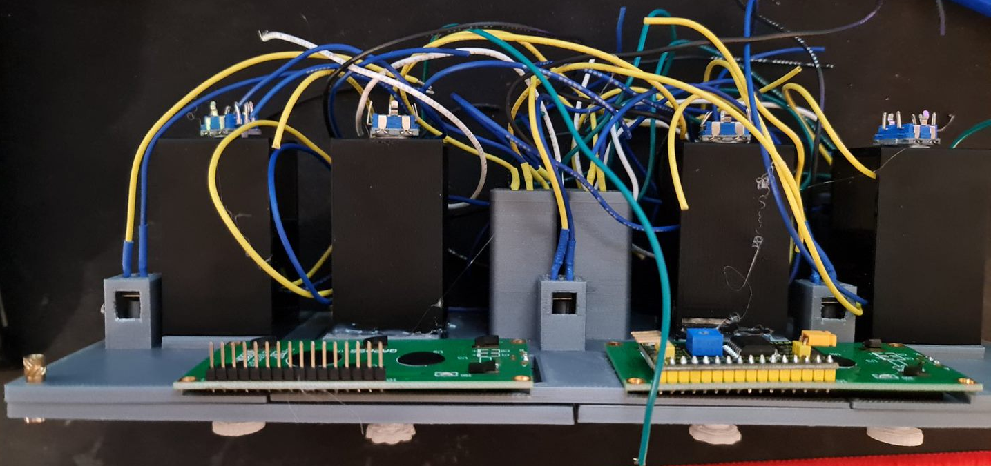
- An Arduino Mega 2560 needs to be wired up. I've got some proto boards ready to solder all the wires to.
- A shell for the components to sit in. This is currently printing whilst typing.
- Printing some Korry labels - this will likely be a transparency on a white sheet of paper.
- Get this all running and working in Flight Simulator, via SimConnect.
- Final decorations - black shroud for the LCD screens for example.
It's fair to say that should this be a repeatable design, I think I would embrace sacrificing imitation for simplicity. For example, the Korry 'pull' action might very well be replaced with additional push buttons on the face. That would then leave the rotary encoders available for a very simple installation. The same applies for the 100/1,000 selector - that might well be a toggle button or a switch. The Korry switches themselves could be made significantly smaller with a larger button - possibly a Cherry MX style key switch. The 1602 LED screens might well stay, although a future version I want to wire up using custom 7-segment displays and LED status lights. None-the-less, it's been a great learning project and hopefully we're only one or two posts away from testing a flight from Melbourne to Sydney.
Designing Korry Switches, Rotary Encoders and a Face Plate for an Airbus A320 Controller
The journey to build a Custom Flight Controller is only just beginning. As mentioned in my previous post, the main component I'm focussing on is getting the Flight Control Unit replicated. This component controls the crucial navigation elements of your flight - namely Speed, Heading, Altitude and Vertical Speed. There are some extra functions available that turn on and off Auto Pilot and Auto Thrust, as well as some expedite buttons and localiser buttons to replicate. There are several buttons to replicate:
- Korry Switches for the buttons in two sizes - 3 large, 3 small
- Rotary Encoders with Push and Pull buttons (most rotary encoders either don't have a button, or have a push only setup)
- 3 Push Buttons for the top layer
- Display with several status lights, ideally with 7 segment displays
For this first prototype in 3D printing all the parts, I have a couple of 1602 LCD screens that will be incorporated into the design instead of the 7 segment displays with lights. This will drastically simplify the wiring - as there are less LED lights and components to make. As I progress, I'm seeing a CNC (possibly with laser) in my future to make things fit better (and the ultimate goal to be backlit).
Korry Switch Design
The Korry switch design on the Airbus A320 requires two status lights for a single push button. Several options exist if you do a casual YouTube or Yeggi search - I've decided though to give the design a bit of a go.
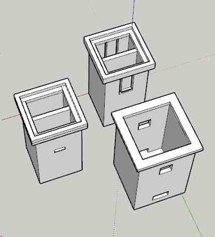
With a bit of tweaking and some test prints, the design that has worked the best includes the outer shell (bottom right) and the inner shell (left). Inside the inner shell, I'll place a single LED light in each chamber. These will be from some of the leftover WS2812b strip I had left over from the Christmas Lights display. These are thin and stupidly bright, so they'll penetrate white plastic fairly easy for this project. I'll also print something of a paper face (maybe a transparent inkjet sheet in future) and do some testing. At the bottom of the outer shell will be a Push button. The 'spring' mechanism in the button will push back on the plastic returning it to the off position and those clips will prevent the button from pushing straight out again. After 3 test prints, and some adjustments to the position of the holes and clips, I'm pleased with the result.
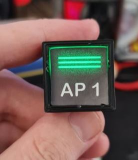
With a bit of tidy up, a transparent sheet and better paper - these switches will fit nicely in the design.
Rotary Encoder with Push and Pull Action
This one was a little more complicated, and a design I'll probably work on - possibly with Cherry MX switches (or clones there-of). These rotary encoder clones are plentiful on YouTube with plenty of ideas. I can't say I'm bringing much new to the table here, only that I'll be designing these to fit in the cockpit I intend to build. This one took a few more goes at the design but the concept is again fairly simple.
The Rotary Encoder will have a push button. If it didn't, I could still achieve the same with a second Push Button but let's not waste what's already available. That leaves the pull action that will need to be activated somehow. With a loose fit on the encoder - tight enough to turn, loose enough to pull, I should be able to build a mechanism that will - when pulled - activate a push button inside the container. Finally - a stalk that will allow the rotation to occur will be required so the user can set their intended Speed, Heading, Altitude or Vertical Speed.
This took a few goes to getting the position and wheel size right. With a digital calliper, this makes the job easier and to fine-tune it, since it uses about 1m-2m of plastic to print any of the components, I figure it's easier to print, then measure with the calliper as to what I need to change.
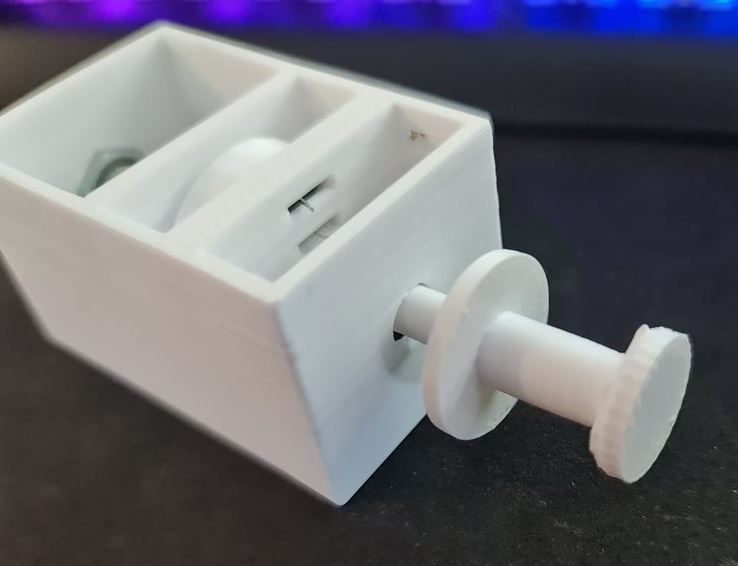
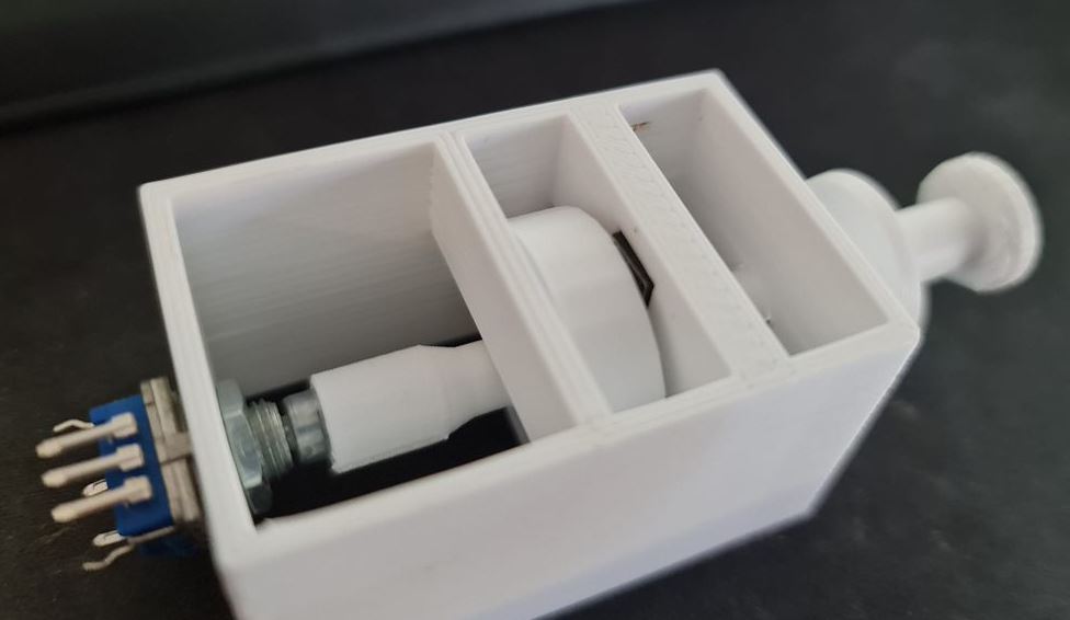
Success! The action works, to a point but the "pull" button is probably not as nice as it could be. So there might still be further modification here before it goes live. Many others use either momentary toggle switches or the larger 12mm square buttons. I have a draw full of different sizes, so we might try something in that space before settling, but definitely some promise here.
For the 100/1000 selector, I've got a few choices in microswitches or toggle switches to try, but these'll come in a future post.
A320 FCU Panel
In designing this one, I note there's a severe lack of vector-image importers for Sketchup Make 2017. My go-to vector tool for years has been Adobe Fireworks which last received an update around CS6. I have a fairly old version of the product but I'm proficient enough in it that vector images are straightforward for me. After some research, I estimate the size of the panel to be 260mm x 90mm. This means that my 200mm x 200mm bed isn't going to fit it all in one. I could do it horizontally if I had the right supports, but I've not yet been successful on my 3D Printer in doing that.
In Fireworks, I prepared a 2600px x 900px vector image and exported it to a format that through some online conversion tools to some pretty legacy formats, got a vector file that I could import into Sketchup. It's not a pretty workflow by any means, and something that probably requires a dedicated post when I can iron out the nuts and bolts of it in something digestible. This Vector file is layered so those colours etc... are visual layers rather than anything particularly useful.
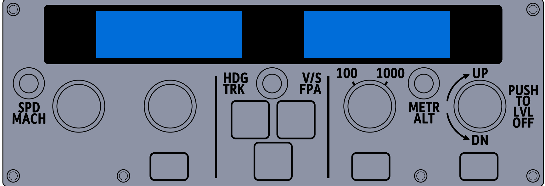
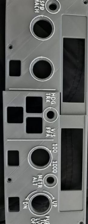
I mentioned earlier that I'd use 2x 1602 character displays and those have been drawn in here instead of the 7 Seg display I'll do at some point in the future. I had to increase the text size to the 5mm in height as identified in the previous post so that it would be legible on the printout. After importing the vector file into Sketchup, the next step was to determine where the 'cut' line will be. I decided to do that on the left part, and straight up the middle of the LCD.
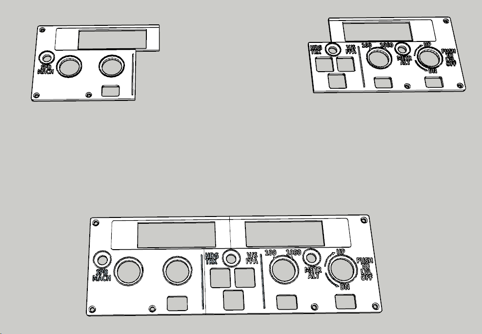
So... now the hard part - determining the best offsets. I settled on 3.5mm for the standard height and an extra 1mm for the text and outlines (which will be painted white after print). So that's what I did. I loaded the printer with some Grey ABS plastic and out comes two pieces albeit slightly warped.
At this stage, I'm pretty happy with how it's coming along, and borrowing a tip from Heli Mech's fantastic video on building similar for a Boeing 737, I bought myself a white paint pen and painted the raised text. And I must say, the results are brilliant - for a 3D Printed job.